Cart is empty.
.png)


Wi-Fi Wireless Relay Board 8 Channels - Web, Telnet, HTTP API, E-mails

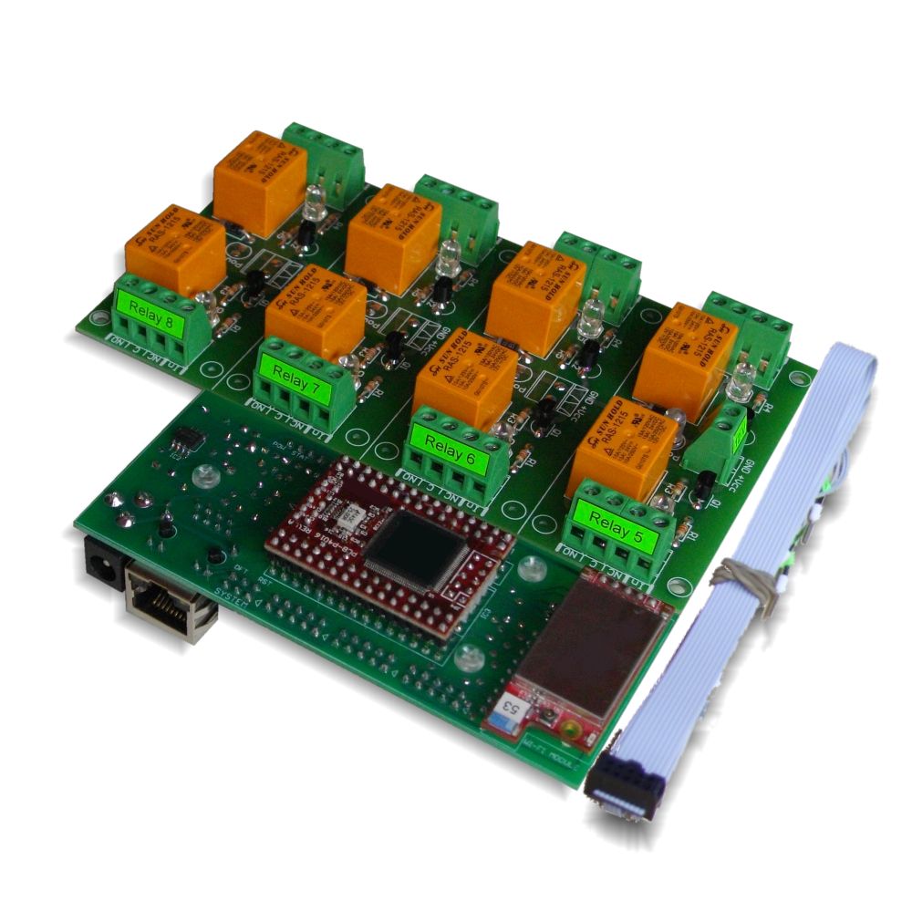

This is WiFi Wireless 8 channel SPDT relay module (board) for remote management and control with Virtual Serial Port, TCP/IP, Web, HTTP API, Telnet and serial commands access. It has 8 SPDT Relays, 8 digital inputs, 8 analog inputs and one UART port. Inputs can be adjusted to control relays (standalone work). Also inputs of one controller can control outputs of another over the LAN/WAN (box-to-box mode). It can send E-mails on inputs change as well. Suitable for remote control, home automation, data acquisition, sensor processing, alarm systems, PLC applications. Works with Home Assistant, Domoticz and OpenHAB home automation systems as well as with Node-RED IoT platform. Now with FREE Android and iOS App!
- Brand: Denkovi Assembly Electronics ltd.
- Weight: 0.500 Kgs
Code: DAE-RB/Ro8-12V + DAEnetIP3-WT
Product Summary
This is a Wi-Fi 8-relay board with additional I/O (8 digital inputs, 8 analog inputs) and a UART, offering Web, HTTP API, Telnet, Virtual Serial, and e-mail notifications. It suits remote control, data acquisition, alarm/security tasks, and box-to-box scenarios across LAN/WAN.
Kit specifications
- 10/100 Mbit Ethernet interface with Link Led. Auto MDIX
- Wireless Wi-Fi 802.11 b/g interface supporting WEP64, WEP128, WPA/TKIP - Personal and WPA2/AES - Personal (Hot-spot is not supported)
- UART interface for RS232/RS485 serial connection with other such controllers. UART can be used also for configuration of the parameters
- Power supply voltage, selectable during purchase:
- 12VDC
- 24VDC
- Power supply consumption (max): 500mA / 12VDC (about 340mA / 24VDC)
- 8 SPDT relay channels (the type depends on the stocks quantity in our store):
- TONGLING - JQC-3FF-S-Z (10A / 250VAC, 15A / 120VAC, 10A / 28VDC)
- SUNHOLD - RAS xx15 (10A / 250VAC, 15A / 120VAC, 15A / 24VDC)
- 1 x 8 digital inputs. Levels: 0-3.3V
- 1 x 8 analog inputs (0 - 2.048VDC input range). Referent voltage: 2.048 V, resolution: 10 bits (for series after 06 Nov 2017)
- On boot the outputs are set with states before reset
- Built in RTC (Real Time Clock). It can be synchronized via NTP manually or automatically each 6 hours
- Capacitor power backup keeps time for days during power failure
- Virtual Serial Port - it may be accessed with Serial RS232 commands over TCP/IP network
- Integrated WEB server with password and features like Ajax parameters reading
- Telnet commands
- HTTP API commands
- TCP/IP ASCII protocol with optional RC4 encryption
- All the network ports can be defined by the user
- Supports ICMP (ping)
- 19 modes for I/O lines such as inverting, timer, pulses, setting output via input and switch ON/OFF according particular time (scheduling)
- Any input may be referred to control any output of this or another controller in the TCP/IP network
- Linearization for the analog inputs
- Box-to-Box (distributed) mode
- SMTP with authentication (SSL is not supported)
- E-mail notifications for various events
- IP address protection
- Power and status led
- Software by Denkovi - DRM Software (Windows/Linux), DAEnetIP3 Configuration utility, Command Line Tool, DAE-iModules App for iOS and DAE-aModules App for Android - New;
- Third party software - more info here;
- Supported by Home Assistant home automation software - New;
- Supported by openHAB home automation software - New;
- Supported by Domoticz home automation software - New;
- Supported by Node-RED IoT platform - New;
- Various software examples - here;
- Various software examples - here;
- DAEnetIP3 documentation: DAEnetIP3 user's manual

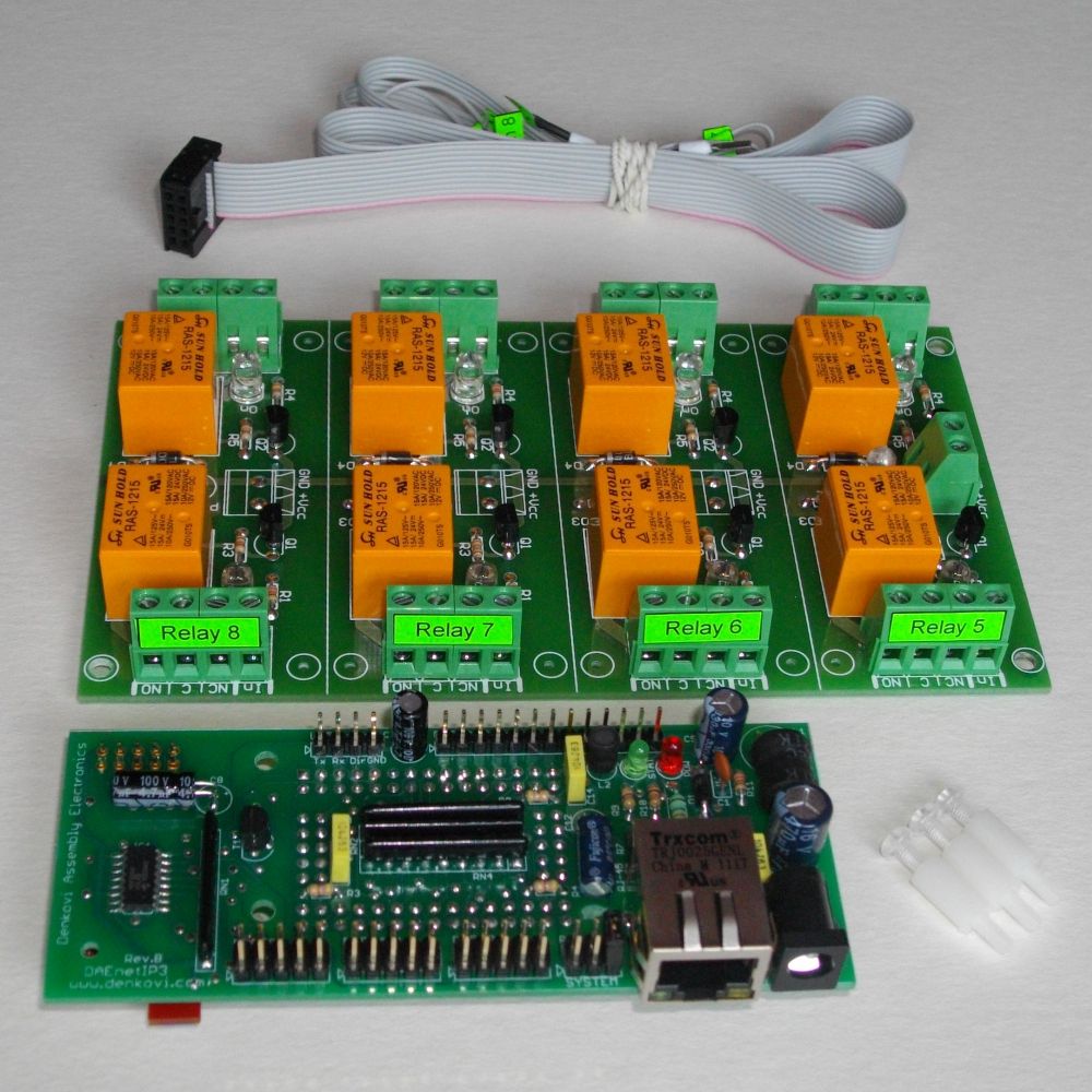
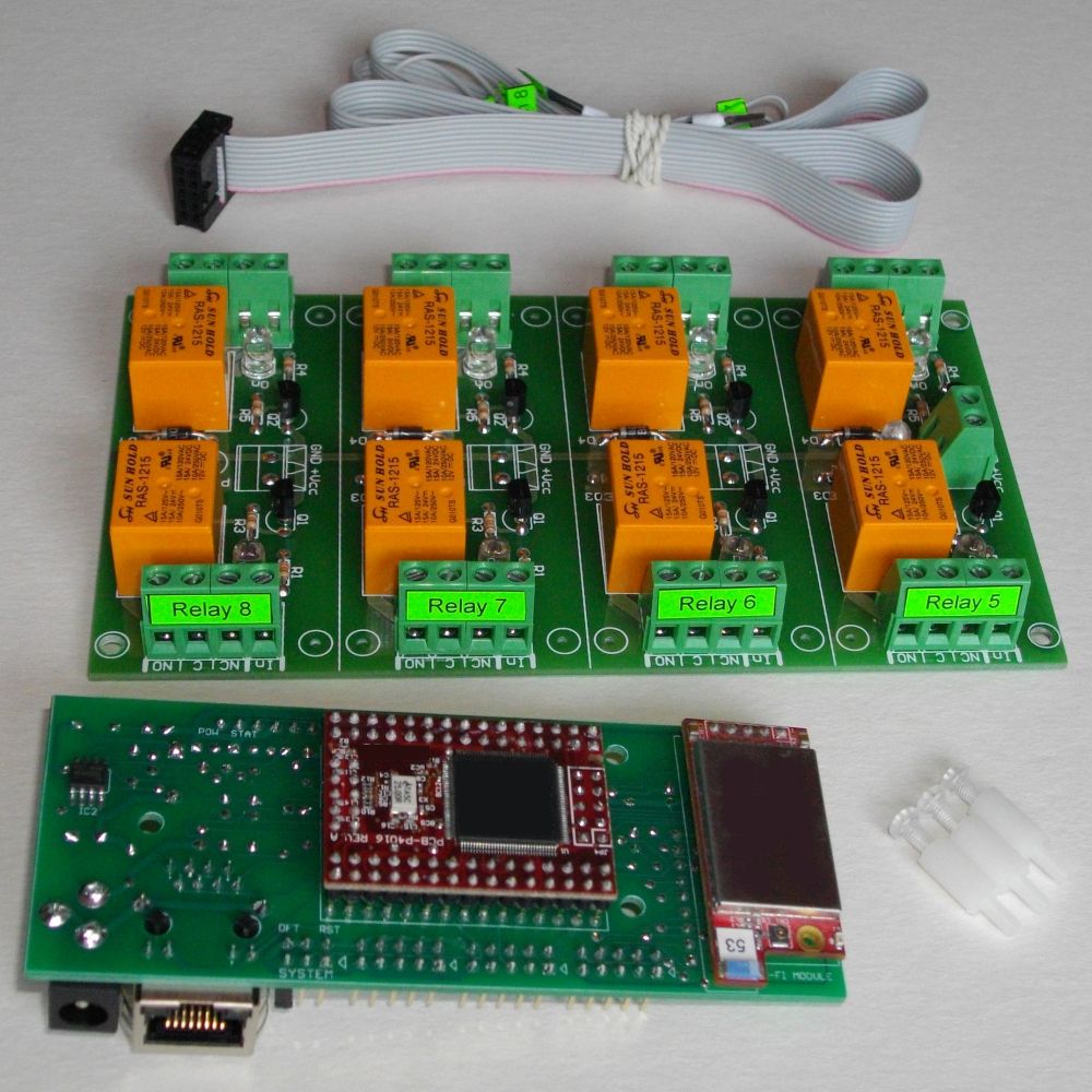
After purchase you will receive:
- 1 x DAEnetIP3 - WT Ethernet controller (Wireless version) - user manual DAEnetIP3_UM.pdf
- 1 x 8 Output Channel Relay Board - link
- 1 x Flat ribbon labeled cabel
- 3 x plastic spacers
- DRM Software - Denkovi Relay Manager Software. The software is available for download from this link -
 setup.exe
Application examples
- Remote electrical devices control
- Sensor information processing (temperature, humidity, distance...)
- Management/monitoring for industrial
- It may be used for simple standalone web based thermostat
- Remote Lock/unlock doors
- Home automation
- Alram applications
- Standalone PLC applications
- Controlling another such device over the LAN/WAN without PC (Box-To-Box)
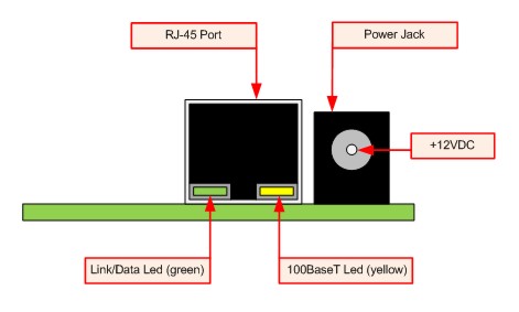
Power Supply
Please pay attention that:
-
The middle pin of the power jack is +12VDC
-
There is not protection against reverse voltage.
-
We recommend to use power supply adaptor that outputs 12 VDC stabilized.
-
Inproper power supply voltage will damage the device!
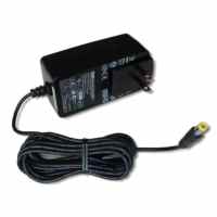
We recommend to use this 12VDC Power Supply Adaptor (SYS1357-2412) that may be found also in our store. Please contact with us if you have questions. We sell the adaptor with one of the AC plugs for: USA, UK, EU, AUS. It is sold separately !
Instuctions
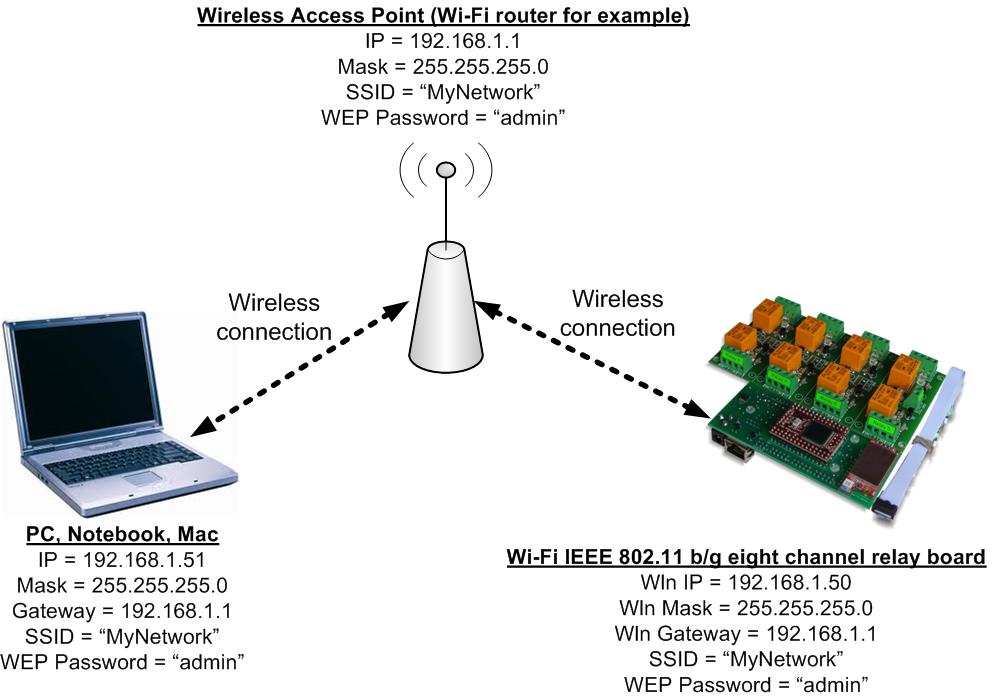
Bellow is given shortcut for instructions how to connect the device DAE-RB/Ro8-12V + DAEnetIP3-WT or only DAEnetIP3 - WX for first time to Wi-Fi router. In the user's manual are shown the rest connection types.
- Connect DAEnetIP3 RJ45 port with UTP (doesn’t matter crossover or straight) cable.
- Connect PC with the other side of the UTP cable.
- Change the IP of LAN card of the PC. It may be for example 192.168.0.1. (DAEnetIP3 is with 192.168.0.100).
- Supply DAEnetIP3 with power supply 12 VDC (the middle pin of DAEnetIP3 power jack is +12VDC). The power led (with red color) must be on.
- Open your browser (IE, Firefox, Opera) and type 192.168.0.100 in the address bar.
- Use admin for password.
- Open Wi-Fi settings.
- Change the Wln IP address of DAEnetIP3. Make it to be in one network with your Wi-Fi network. We accepted the IP of the Wi-Fi network is 192.168.1.X. So the Wln IP of the DAEnetIP3 Wi-Fi interface may be 192.168.1.2. Wln Mask = 255.255.255.0 and Wln gateway is 192.168.1.1 (The IP of your router). Set the SSID and WEP password.
- Click “Save” button.
- Unplug the power supply.
- Remove the UTP cable from the PC and controller.
- Supply again the DAEnetIP3 with 12VDC.
- The orange Wi-Fi status led of DAEnetIP3 must blink initially and then must be on constantly. This means the controller is connected to the Wireless network. If the led is off then DAEnetIP3 is not connected to the Wireless network because some settings are not correct. If so you need to check out the settings again. Also you may restart your router (just in case).
- If the DAEnetIP3 is connected properly, open browser and type 192.168.1.2.
- Now you may access the DAEnetIP3 controller over Wi-Fi.
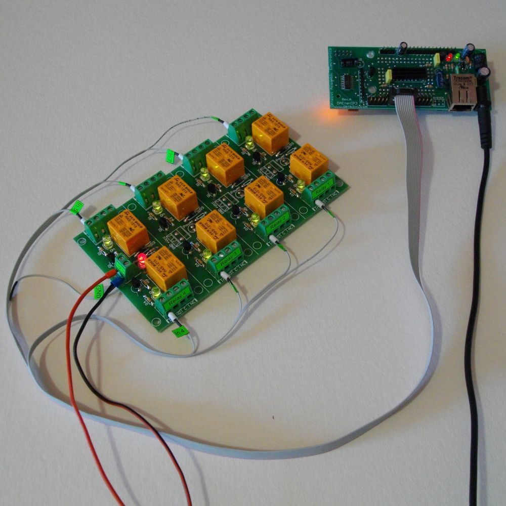
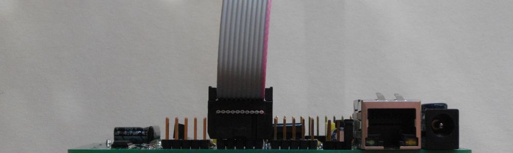
Typical connection of the device
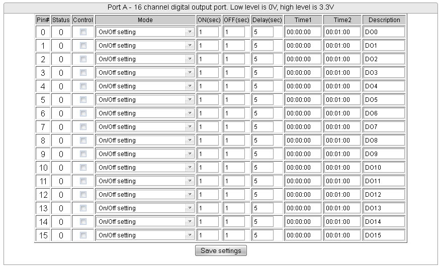
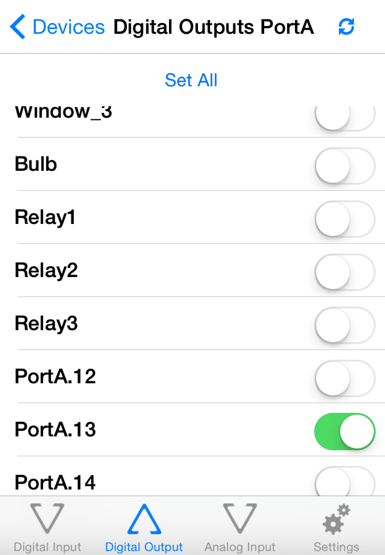
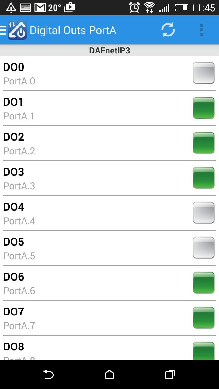
16 x Digital outputs
DAEnetIP3 has 16 digital outputs working in 19 different modes. However the relay board has only 8 relay outputs. So to set the relays you need to change PortA.0 - PortA.7. Relay1 is connected to PortA.0, Relay8 to PortA.7. On the PCB this is marked as PortA_1. When the output level is 0, the relay is OFF. When it is 1, the relays is ON.
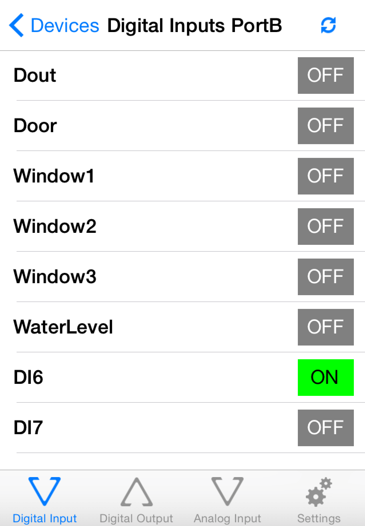
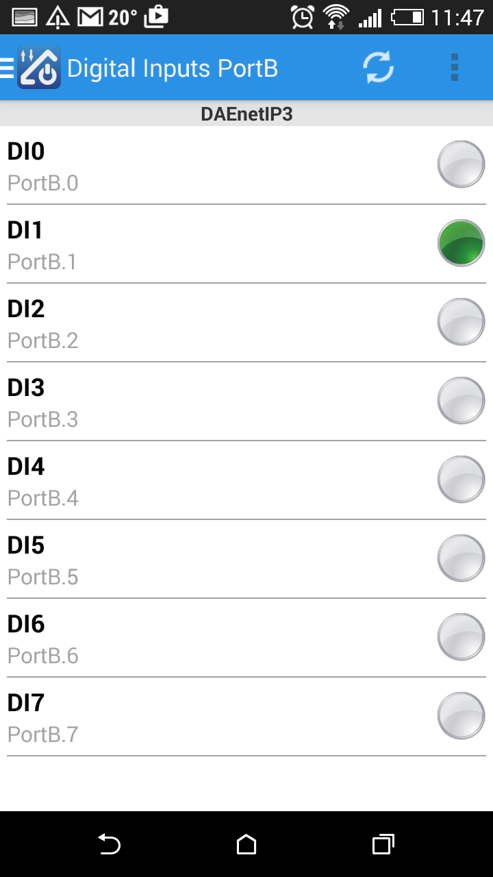
8 x Digital outputs
DAEnetIP3 has 8 digital inputs. They work with +3.3V logic (Low level is 0V, high level is 3.3V). They work in 3 different modes. When the controller digital inputs pins are not connected the pins are in high level (there is connected pull up resistor 10K to each digital input). The input may be tracked only, may control some PortA digital output (this means the relay board also) by rising/falling edge or it may control even output from another DAEnetIP3 controller (connected in the same Ethernet network).

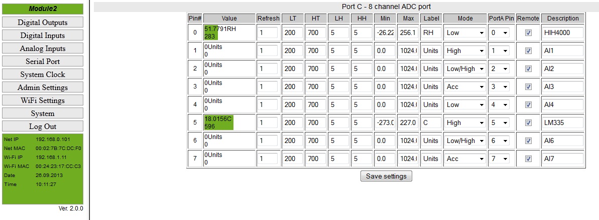
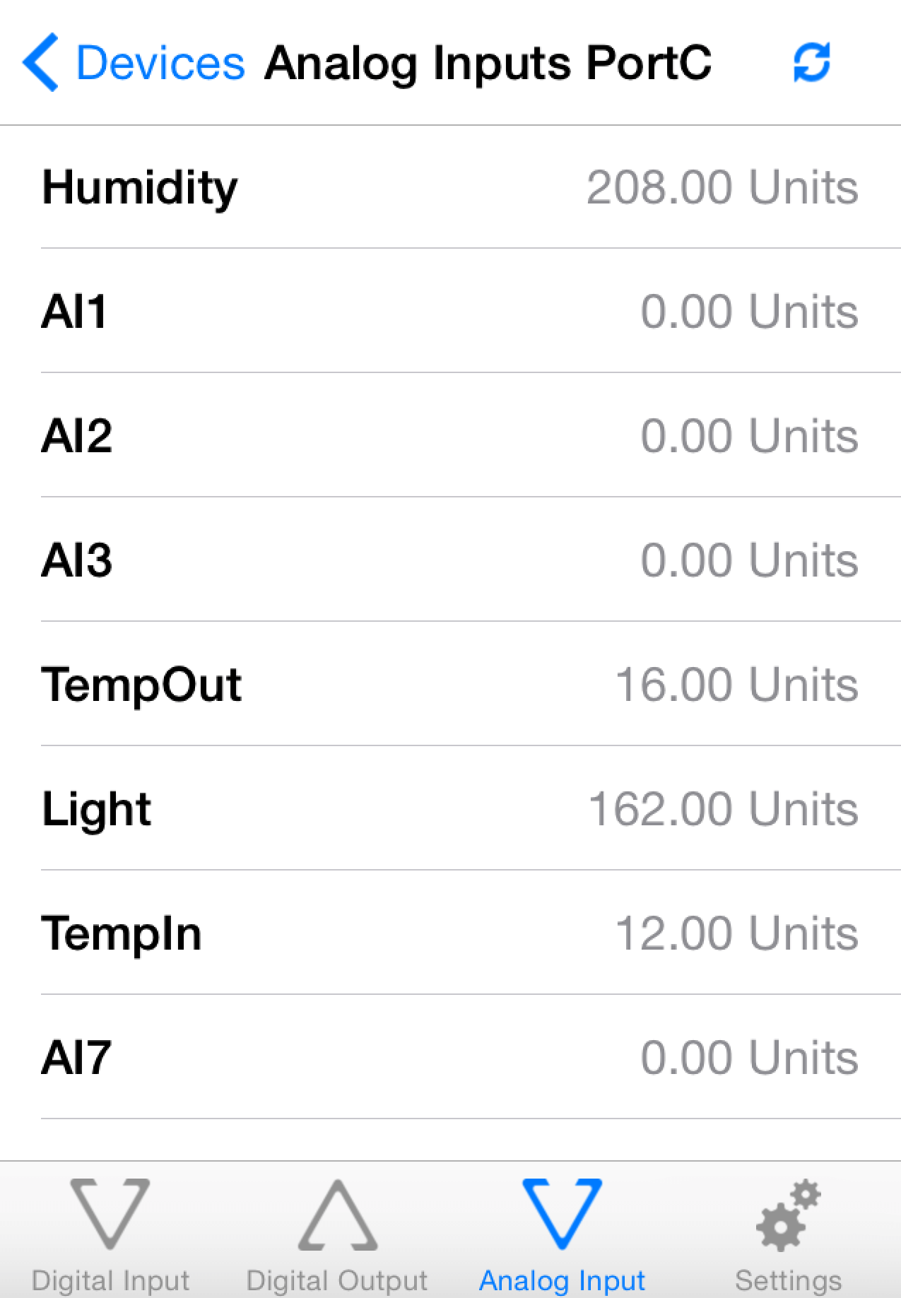
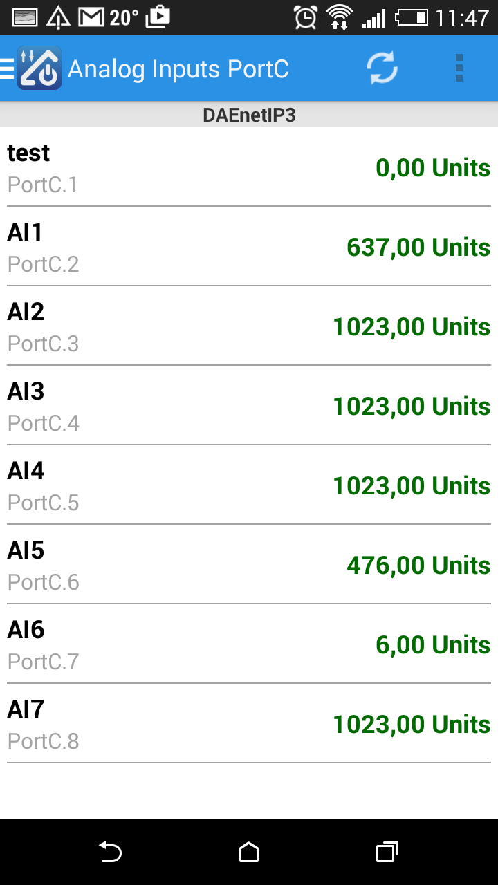
8 x Analog inputs
DAEnetIP3 has 8 analog inputs with 2.5 VDC reference voltage source and 1024 bit resolution.
The input may be tracked only, may control some PortA digital output (this means the relay board also) by crossing threshold or it may control even output from another DAEnetIP3 controller (connected in the same Ethernet network).
It is possible also each analog input to be linearized (i.e. to be retreived directly desirable units).
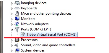
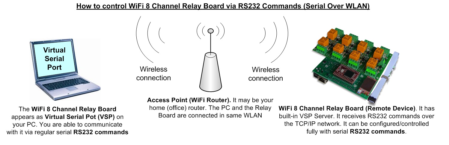
Access via Virtual Serial Port
DAEnetIP3 and all devices that are based on it may be accessed/controlled via Virtual Serial Port. In other words the the device in this auction may be accessed via COM Port RS232 commands from your computer because it will apear as COM Port:
- DAEnetIP3 appears as VSP (COM Port) on your PC
- It may be accessed with any Serial Terminal (for exaple HyperTerminal)
- The only thing the user has to do is to send and receive commands via the COM Port. All the TCP/IP commnucation is done by the driver.
- There is not matter if your DAEnetIP3 device is connected to your PC over LAN cable or Wireless Wi-Fi network, it will appear as VSP (COM Port) on your PC. You need to set only the proper IP, Port and COM Port Name.
Example commands and responses that are sent/received via the DAEnetIP3 VSP (COM Port). The serial address of DAEnetIP3 is 00.
- Get Digital Input 1 level (Din1), counting in the commands is zero based:
- Send: 00BV0=?;
- Receive: 00BV0=0; //The level is low
- Get Analog Input 1 level (Ain1), counting in the commands is zero based:
- Send: 00CV0=?;
- Receive: 00CV0=512;
- Set Digital Output 12 (Do12) in High level, counting in the commands is zero based:
- Send: 00ASB=1;
- Receive: 00ASB=1;
- Get the Ethernet IP address of the module:
- Send: 00MIP=?;
- Receive: 00MIP=192.168.0.100;
All the commands are described in the DAEnetIP3 user's manual
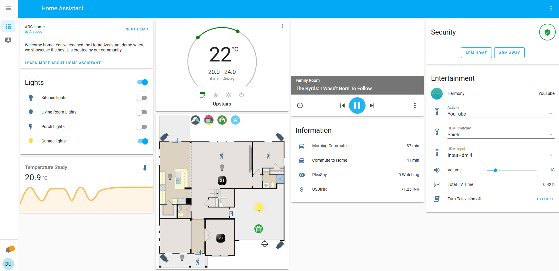
Access from Home Assistant
Home Assistant is very powerful home automation system. Please checkout our application note for more information.
Access DAEnetIP3 from OpenHAB
OpenHAB is a third party open source free home automation software. Run your server on Linux, macOS, Windows, Raspberry Pi, PINE64, Docker, Synology... Access it with apps for the web, iOS, Android and others. Use a powerful and flexible engine to design rules, with time and event-based triggers, scripts, actions, notifications and voice control.
The communication way is done via HTTP GET requests. More information about the integration with our hardware - http://denkovi.com/openhab-with-denkovi-modules or contact with us.
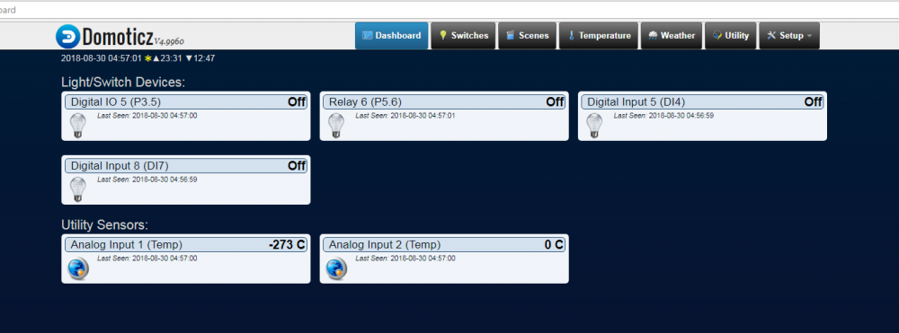
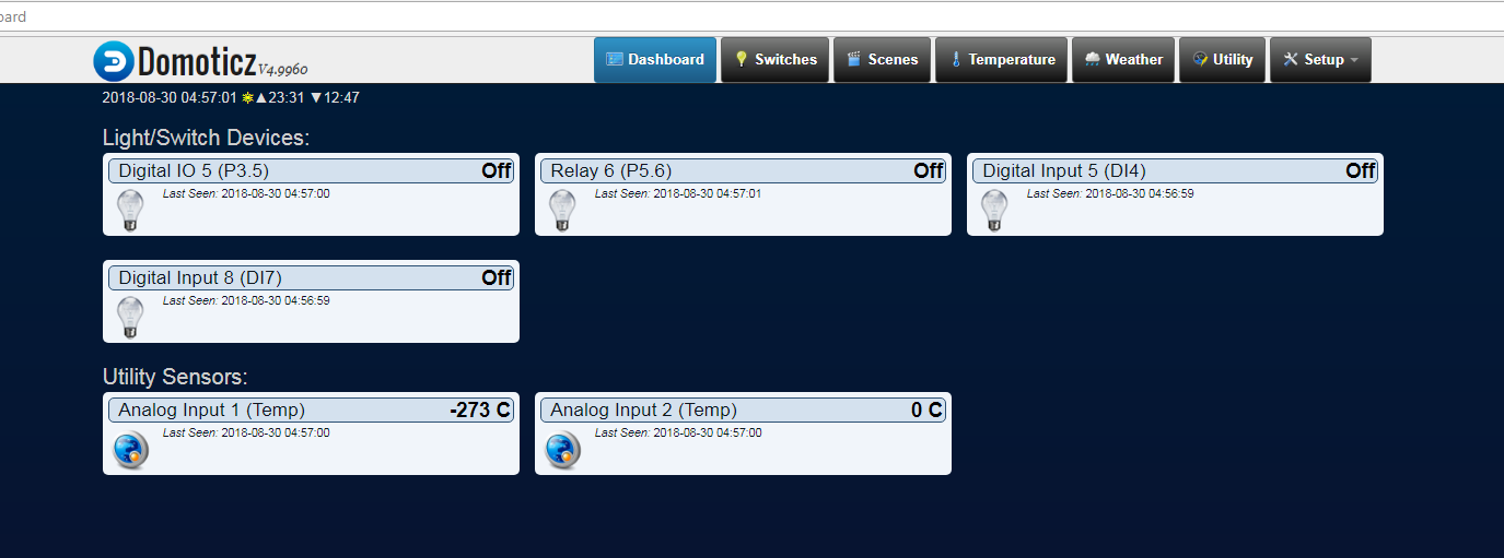
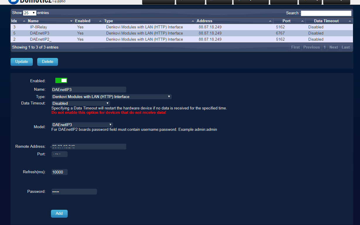
Access DAEnetIP3 from Domoticz
Domoticz is a free open source popular home automation software which can run on Windows, Linux, MAC, Rasberry PI and others. It is a home automation system design to control various devices and receive input from various sensors. Access it with apps for the web, iOS, Android and others.
More information about how to connect and use it with our hardware - http://denkovi.com/domoticz-with-denkovi-modules or contact with us.
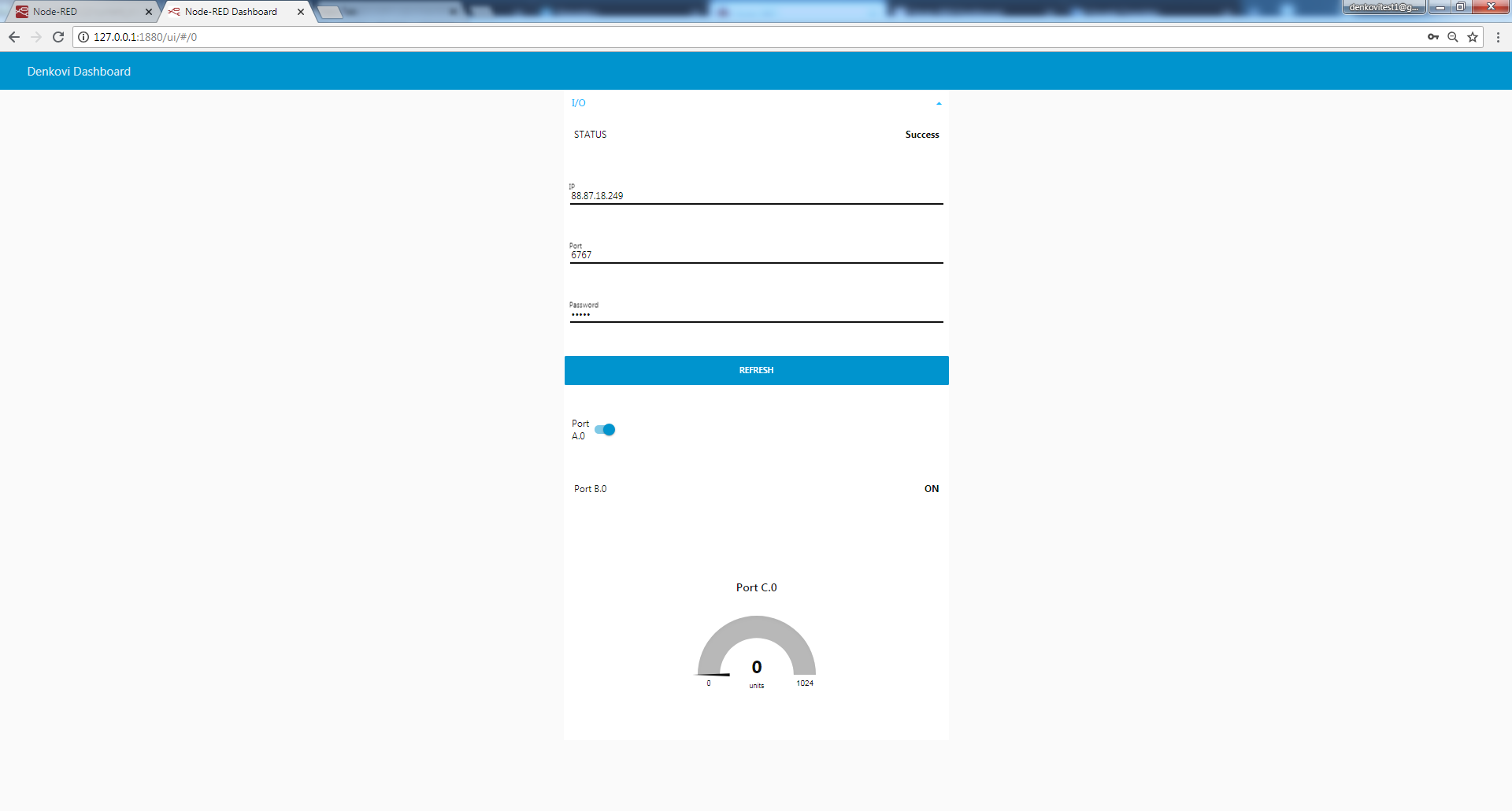
Access DAEnetIP3 from Node-RED
Node-RED is a flow-based programming platform for the Internet of Things. We prepared small example for communication between Node-RED and our device. More info about Node-RED and denkovi modules: here
You can download the example Node-RED flow from here for HTTP GET Requests
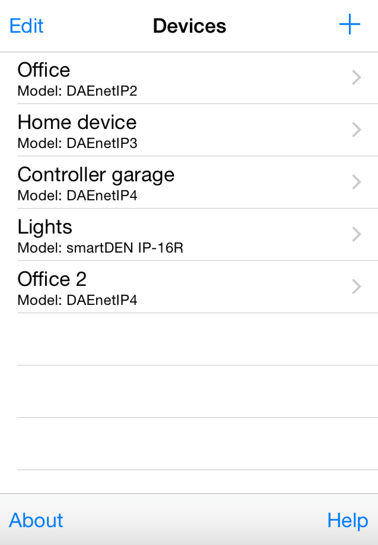
Access DAEnetIP3 from mobile devices
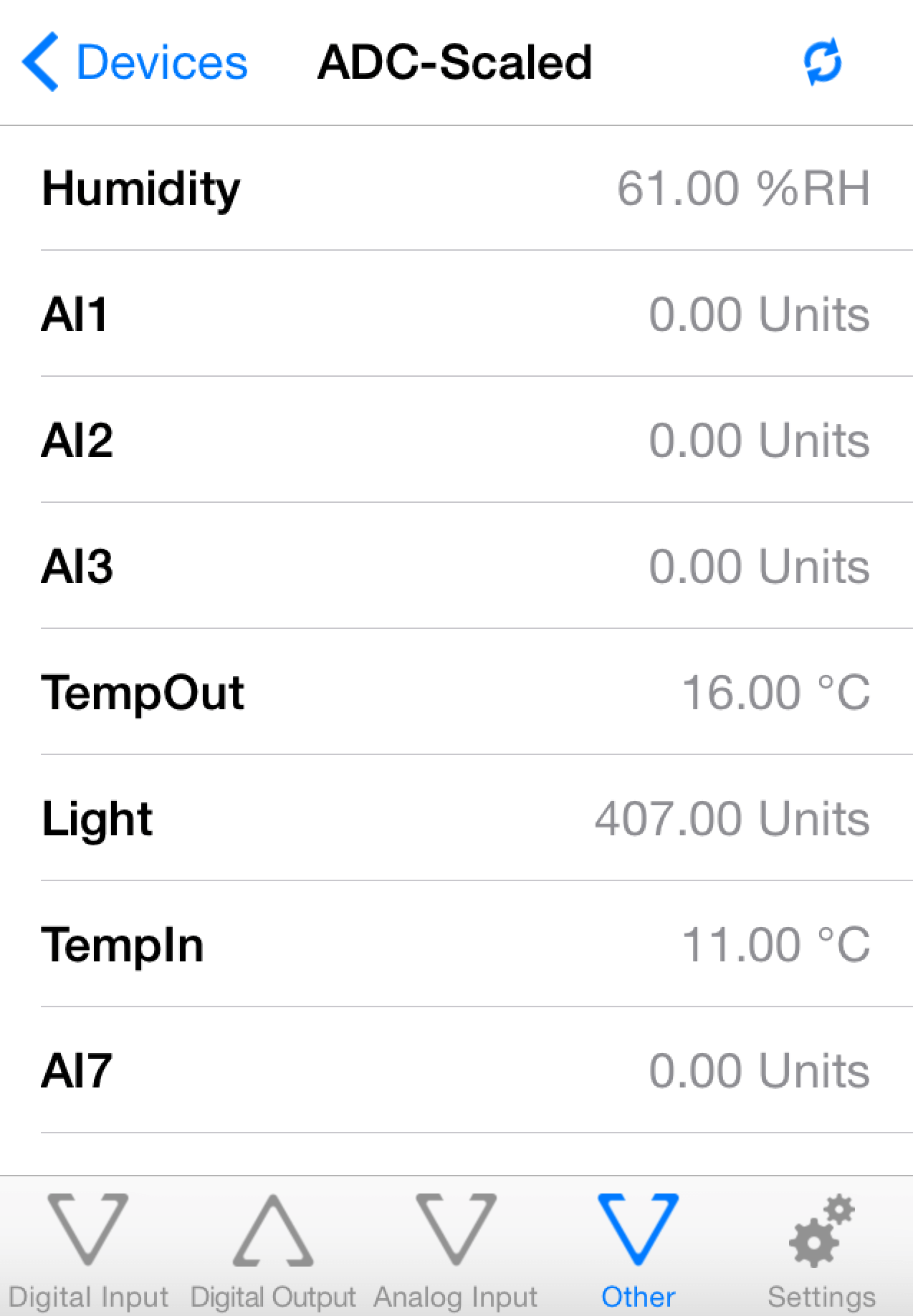
iOS App DAE-iModules

![]()
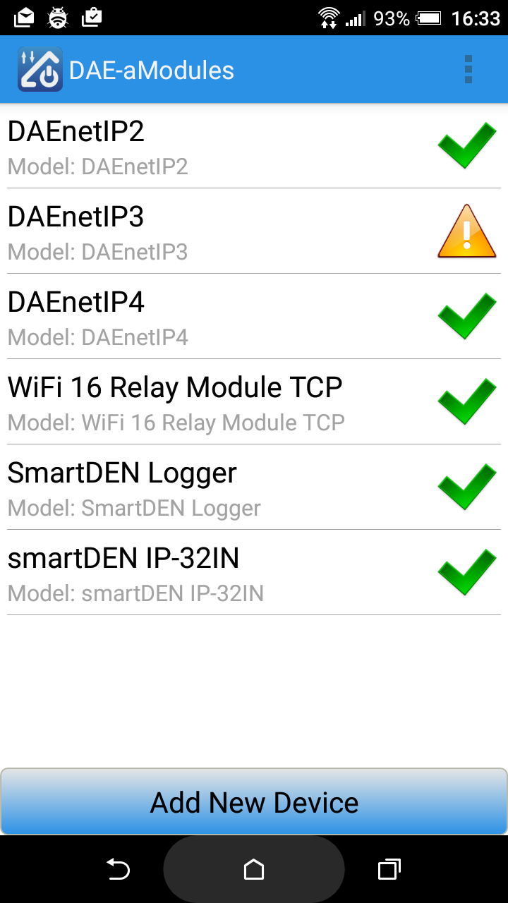
Android App DAE-aModules


The video bellow shows how you can control DAEnetIP3 based device - Wi-Fi 12 Relay Module. Any other Denkovi Ethernet Device from this list can be acessed with same success from your iOS device via DAE-iModules
![]() Some useful information about DAE-iModules and DAE-aModules and DAEnetIP3:
Some useful information about DAE-iModules and DAE-aModules and DAEnetIP3:
- Select device DAEnetIP3. Enter the IP, HTTP Port and web password for the device
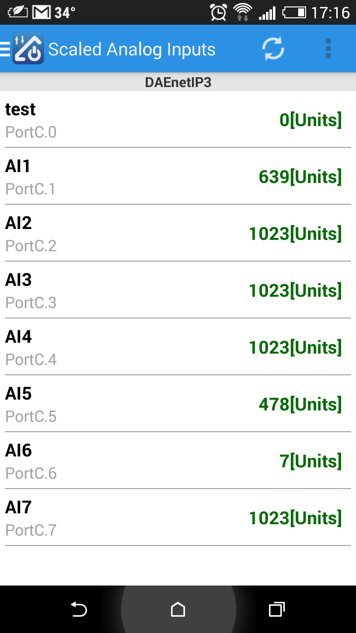
- Tab "Other inputs" contains the analog input values for the hardware linearization (by DAEnetIP3) while tab "Analog Inputs" shows their original values
- To connect and scale the analog inputs with sensors, please refer to this link: http://denkovi.com/connecting-analog-sensors-to-daenetip3
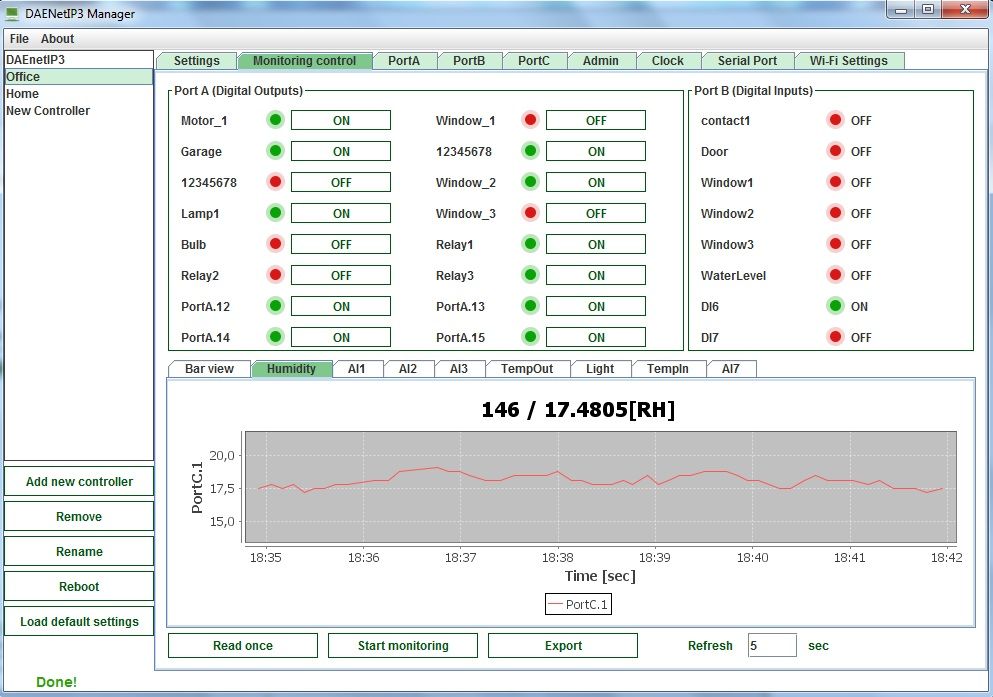
Access via DAEnetIP3 Manager
A free utlity for all DAEnetIP3 based modules for controling, configuration, monitoring and log all the DAEnetIP3 parameters.

Download and documentation - here
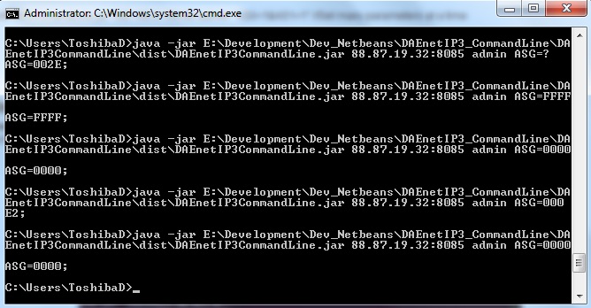
Access via DAEnetIP3 Command Line Tool
Windows/Linux/osX command line tool create especially for DAEnetIP3. It allows easy integration of the DAEnetIP3 into third party software, control from command promt, control from bat files, from bash scripts, from shortcut and others. For more info and download here: http://www.denkovi.com/daenetip3-command-line-tool
Access via DRM Software
The device is supported by DRM Software. DRM Software is Windows/Linux software for controlling all our relay boards. Supported OS:
Windows: tested on XP, Vista, 7 and 8
Linux: tested on Ubuntu and OpenSuse
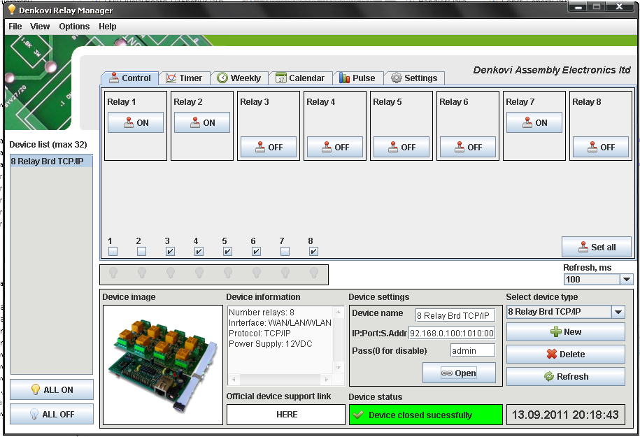
DRM Software image - control mode for Ethernet TCP/IP Eight Channel Relay Board
![]() For more information about DRM Software, documentation and download - here
For more information about DRM Software, documentation and download - here
![]() Download the last version (install package) - DRMsetup.exe
Download the last version (install package) - DRMsetup.exe
![]() Download the last version (intstall archive) - DRMsetup.rar
Download the last version (intstall archive) - DRMsetup.rar
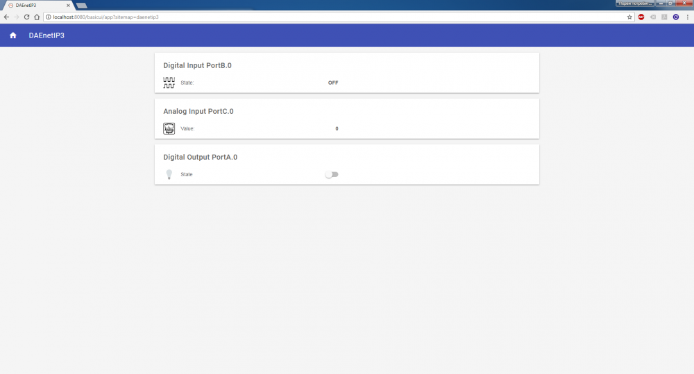
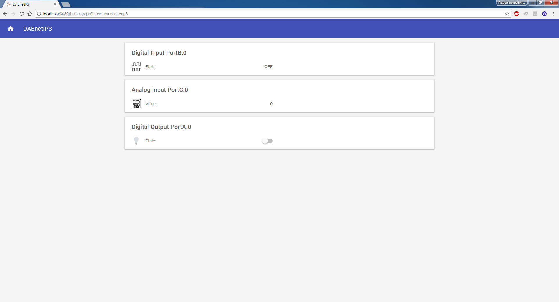
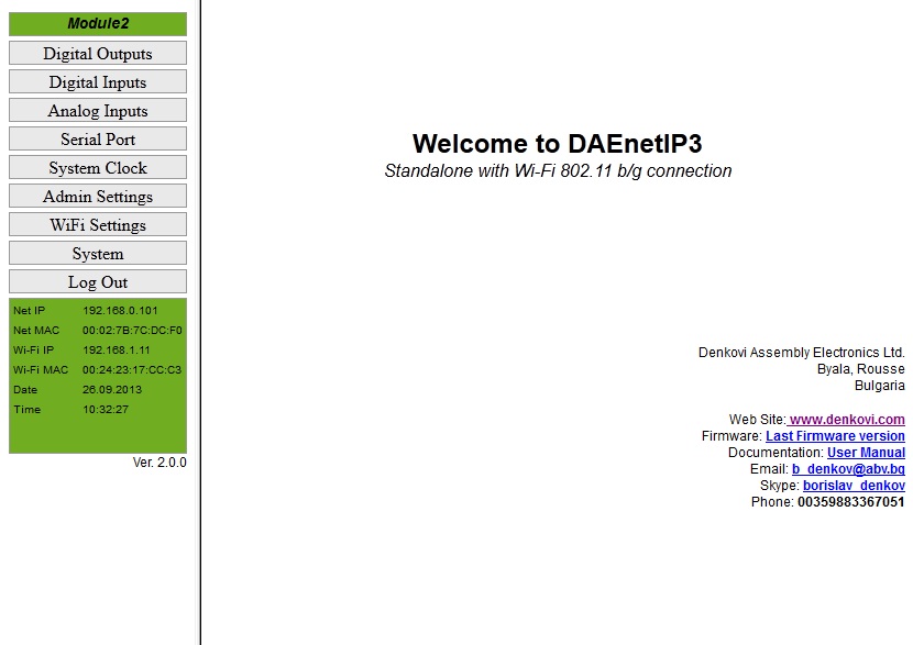
Access via Web
DAEnetIP3 has built-in web server for configuration. All the parameters can be accessed via web browsers like Mozilla, IE and Opera. The pages for I/O ports are refreshed automatically. In this way it is possible to track all the I/O states in real time without manually refreshing the page. The web browser must support JavaScript.
The page below the text shows the page for the analog inputs. Their states are automaticaly refreshed each 2-3 seconds. The user doesn't have to click refresh button each time but just tracks the I/O changing values almost in real time (Ajax).
Access via HTTP API commands
Bellow are shown example commands. Please note that there is HTTP API password (by default it is admin) to prevent unauthorized access.
Example commands:
send: http://your.ip.address/command.html?P=admin&ASG=?& (get the whole PortA status of DAEnetIP3)
receive: <!DOCTYPE html><html><body>ASG=0F0F;</body></html>
send:http://your.ip.address/command.html?P=admin&ASG=?&BVG=?&CV0=?& (send several commands at a time)
receive: <!DOCTYPE html><html><body>ASG=FFFF;BVG=0F;CV0=12;</body></html>
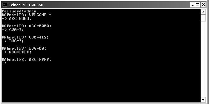
Access via Telnet
DAEnetIP3 can be easily accessed via Telnet. Simple password protection mechanizm is provided. Note that Telnet is not secure protocol, so it is recommend using only in secure networks.
On the figure right to the text is shown how DAEnetIP3 controller with IP address 192.168.1.50 is accessed via Telnet with Windows XP.
- Open command line and type: telnet "Controller IP"
- Use the passowrd, in our case this is admin. After correct login the controller responds with welcome message.
- The first command is ASG=0000; - it sets all 16 DO in low level.
- CV0=?; gets the ADC channel 0 value. Its 415; It may be from 0 up to 1023.
- BVG=?; gets the eight digital inputs levels. Its 00, which means all inputs are in low level
- ASG=FFFF; Sets all the 16 DO in high level.
Ofcourse these commands are only small part. The full list may be found in the documentation.
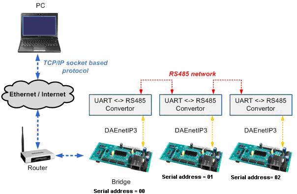
Access via Serial Line (UART or RS485)
Each DAEnetIP3 controller may be accessed via UART serial communication. The protocol is given in the documentation. This is provided in case you need RS485 network for example accessed only with one IP address. Each controller has serial address, that is given in each packet sent to the server bridge from user software. The figure below to the text shows how 3 DAEnetIP3 controllers are connected in serial network using UART <-> RS485 convertors (not included in the auction). The serial network may be accessed over LAN, WLAN or WAN with user TCP/IP socket based software.
Access via TCP/IP socket
DAEnetIP3 controller has possibility for access via TCP/IP socket. The user may connect with custom software to port that is defined for socket based TCP/IP communication.
The protocol is not based on some standart, but it is developed especially for the DAEnetIP3 controller. The full description of the protocol may be found in the user manual.
The reason for creating such communiation way is that TCP/IP sockets are widely used in all programing languages.In this way you may create software for DAEnetIP3 without learning difficult and heavy protocols.
The controller supports RC4 encryption/decription for the TCP/IP socket comunication. This is security measure that gives you basic protection.
Another security option is IP address protection, that allows only one IP to access the DAEnetIP3 via Web, Socket and Telnet.
More videos
Demo video - DRM Software and Ethernet TCP/IP Eight Channel Relay Board
Links
Denkovi software
- DAE-iModules - App for iOS mobile devices, support link here
- DAE-aModules - App for Android mobile devices, support link here
 DAEnetIP3 Manager - here
 DRM Software - software for controlling relays - here
 DAEnetIP3 Command Line Tool - here
 Home Assistant - This device is supported by Home Assistant. For more information - please follow this article.
 Domoticz - This device is supported by the powerful home automation system Domoticz. Please take a look at our application note for more information - http://denkovi.com/domoticz-with-denkovi-modules
 openHAB - This device is supported by the powerful home automation system openHAB. Please take a look at our application note for more information. You can also download the configuration files for openHAB (ver 2.2.0) for communication via HTTP GET requests.
 MajorDomo - Innovative home automation system. It has web interface, voice control, notifications, GPS tracking and many more features. More information - here
 MyDomoticaHd - Android software by www.phsoftware.altervista.org. Additional explanation how to use the software with our ethernet relays and ip controllers - here: http://denkovi.com/mydomoticahd-with-denkovi-ethernet-relays
Please note that TFTP firmware upgrade is not anymore supported. From our experience we don't recommend to use it because it is unsafe and can damage your DAEnetIP3 controller.
| Date | Version | Notes |
| 6 Oct 2013 |
2.0.0 |
New features and bug-fixing list: here. The controller will be shipped with this version. |
| Sep 2011 | 1.0.0 | The initial release (documentation for 1.0.0 version) |
| Date | Changes |
| 06 Nov 2017 |
Series produced after this date are with:
|
 Node-RED IoT platform - example communication flow with HTTP GET Requests. More about Denkovi modules and Node-RED: here.
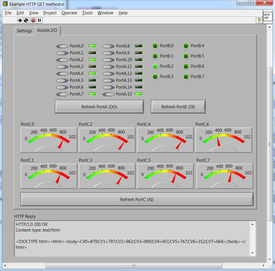
 LabVIEW 2011 - Example how to set/get the DAEnetIP3 I/O status via HTTP GET requests. The code is not public, but a download link will be sent to your email after purchase.
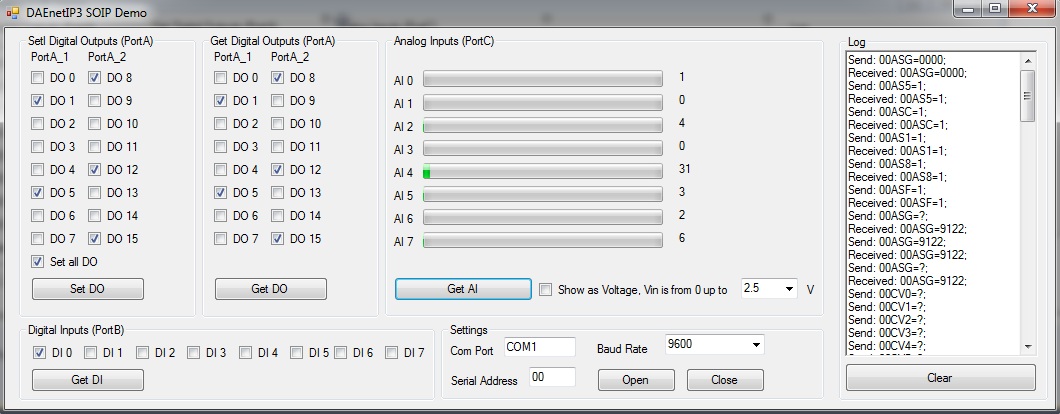
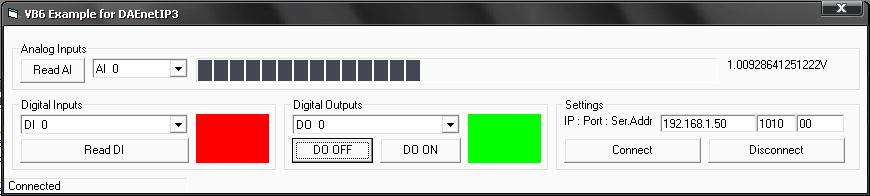
 VB.NET Express 2010 (screenshot) - Example how to access DAEnetIP3 via Virtual Com Port (VCP). There is tutorial how to do this - here. The executable file is here.
- VB.NET Express 2010 - Examples how to access DAEnetIP3 via sockets.
- C#.NET Express 2010 - Example how to access DAEnetIP3 via HTTP GET commands.
- C++.NET Express 2010 - Example how to access DAEnetIP3 via HTTP GET commands.
 Visual Basic 6: Example1 (TCP socket) - acess the I/O lines (does not include RC4) download. Example2 (HTTP GET Requests) - communicate with the module using HTTP get requests.
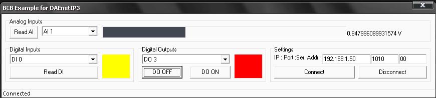
 Borlnad C++ Builder 6 (screenshot) - Example how to acess the I/O lines (does not include RC4) - download.
 Java (using TCP/IP sockets) - Example how to acess the I/O lines (does not include RC4) - download.
- Java (using HTTP/API) - Example how to acess the I/O lines (does not include RC4) - download.
 Node.js (HTTP GET Requests) - example how to communicate with the module using HTTP get requests in Node.js.
 Python - Example how to set/get the device I/O status using HTTP GET requests
Wi-Fi controller + relay
Wi-Fi 8 relay board
wifi relay
-

-
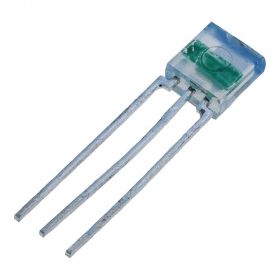
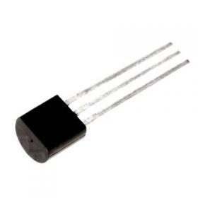
TSL250R light to voltage sensor
TSL250R light to voltage optical sensor, photodiode, supply range: 2.7 - 5.5V DC
Price: $12.40Out of stock -
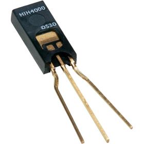
HIH-4000-02 humidity sensor, range:0÷100% RH
Humidity near linear voltage output sensor HIH-4000-02
Price: $40.30 -
-
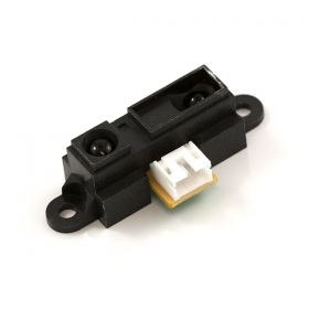
Infrared Proximity Distance Sensor - Sharp GP2Y0A21YK, 10-80cm
GP2Y0A21YK is infrared proximity sensor made by Sharp. It has analog output from 3.1V at 10cm to 0.4V at 80cm which make it suitable for using along with our modules
Price: $23.65 -

Split Core Current Transformer with 0-5V DC output
A split core current transformer which is able to produce a 0-5V DC signal with an AC primary current (from 5 to 50A selectable). The split core allows the transformer to be clipped on to a wire without disconnecting the primary current carrying wire.
Price: $19.95 -
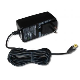
SUNNY SYS1541-2412 Switching AC Power Adapter 12V/2A Out
This is power supply adapter suitable for all denkovi 12VDC devices. Its AC plug may be changed, so please specify the type of the plug you want to use and we will send it with this AC plug. We offer AC plugs for USA, UK, AUS and EU.
Price: $26.40 -
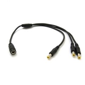
SUNNY DC Power Cable Spliter 1x3
A DC power cable spliter 1x3, suitable for all our products with power jack 2.1mm
Price: $7.10 -
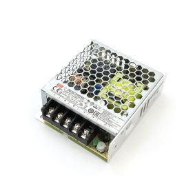
Mean Well LRS-35-12 Single Output Switching Power Supply 12V/3A Output
A 35W single-output enclosed type power supply with 30mm of low profile design. Input range is 85-264VAC, output is 12VDC / 3A. Suitable for all 12V Denkovi devices.
Price: $28.60


