Cart is empty.
.png)


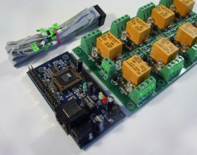
Web SNMP controlled 4 Relay Board

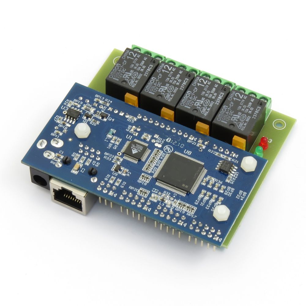
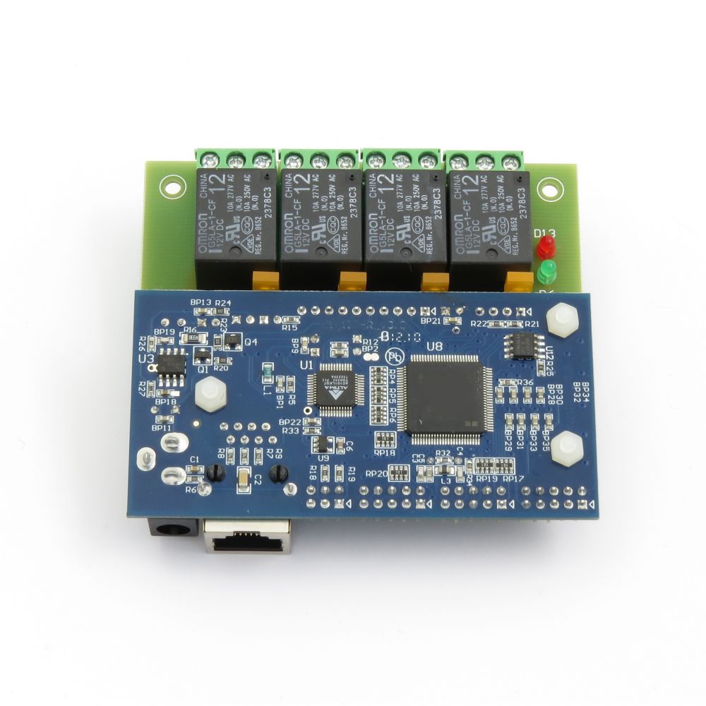

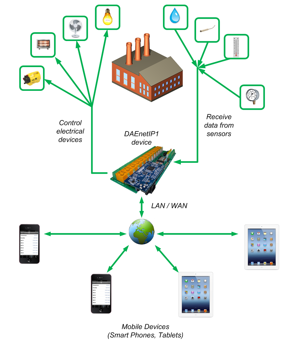
This is relay card based on DAEnetIP1 snmp controller with 4 SPDT channels. Additionaly it has 8 digital outputs, 8 digital inputs/outputs and 8 analog inputs. Connecting the snmp relay board into your local network allows to control electrical devices from another computer or mobile smartphone (tablet) from any location all over the world. You may control it via DAEnetIP1 Manager, command line, browser or Smartphone. For developers we provide software examples in Java, .NET, Labview, PHP. The relay card can be used for home automation, industrials, sensor monitoring or embedding in larger systems.
- Brand: Denkovi Assembly Electronics ltd.
- Weight: 0.150 Kgs
Code: DAEnetIP1 + DAE-RB/Ro4_v2
Features
- 10/100 Full duplex Ethernet interface (Auto MDIX)
- Power supply 12VDC / 250mA
- 4 x SPDT relays OMRON G5LA-1-CF
- 8 x digital outputs (0-3.3VDC)
- 8 x analog inputs with 10 bit resolution (0-2.5VDC) with pull-down resistors
- 8 x configurable digital I/O port (0-3.3VDC)
- Hardware "Pulse" function for the digital outputs
- Standart protocols: ARP, IP, ICMP (ping), DHCP
- Supports snmp v1 (snmpset, snmpget, snmptrap), HTTP (web server with autorization) , TFTP (for firmware upgrade)
- Port for SNMP (161) can be changed
- It can be configured with SNMP requests or web browser
- Integrated WEB server for all functions/parameters access
- Reset of the digital outputs on incoming/outgoing ping timeout
- Function "load outputs states from EEPROM on boot"
- Each I/O line can be named by user via web browser/snmp
- It can send traps according analog ADC level
- An analog input may be referred to control a digital output according its input level
- Onboard temperature sensor
- Possibility of connection analog sensors to the analog inputs as LM34DZ, LM35DZ, LM335, MCP9700A
- Denkovi software: DAEnetIP1 Manager
- 3rd parity software: Command line utility - netsnmp
- Software examples: .NET, Java, Labview and PHP
 DAEnetIP1 user's manual: download
Application examples
- Home Automation
- Security and fire alarm systems
- Manual or automatic device restart if event occur
- Management/monitoring for industrial
- Sensor information processing
- Remote electrical devices control
- Remote Lock/unlock doors
- Suitable for school and university education
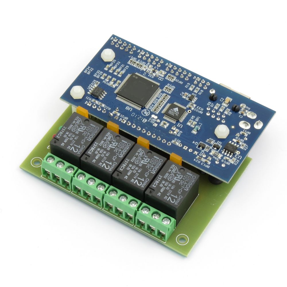
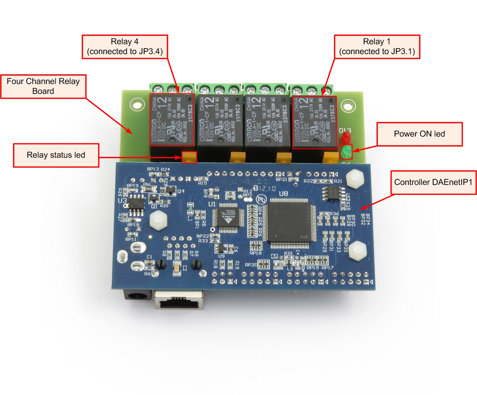
The package includes:
- 1 x DAEnetIP1 Ethernet controller
- 1 x Four Channel Relay Board peripherial board
- 3 x plastic spacers
- The module will be shipped assembled and tested
Device diagram
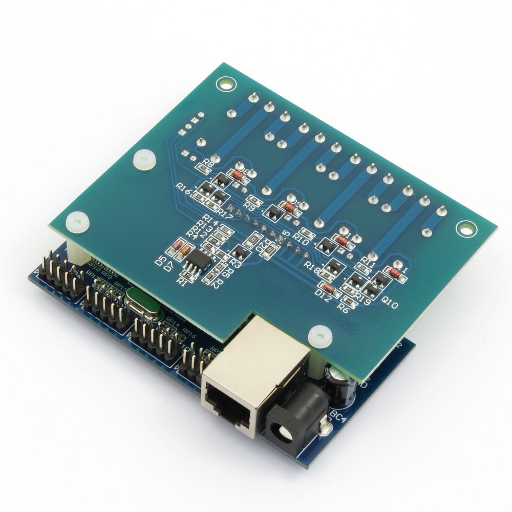
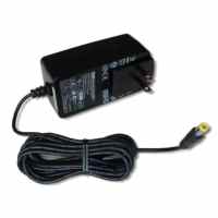
Power supply requirements
- 12VDC / 200mA - center positive tip.
- DAEnetIP1 does not have reverese polarity protection.
- We recommend to use this 12VDC Power Supply Adaptor (SYS1357-2412) that may be found also in our store. Please contact with us if you have questions. We sell the adaptor with one of the AC plugs for: USA, UK, EU, AUS. It is sold separately !
Connecting analog sensors to DAEnetIP1
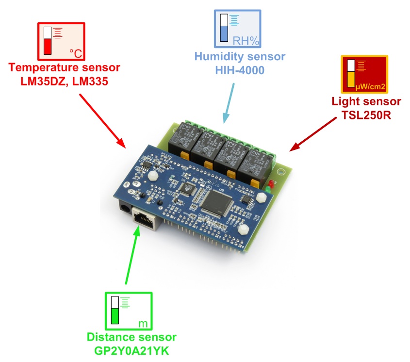
More information how to connect different types of analog sensors to the SNMP 4 Relay Board -
http://denkovi.com/connecting-analog-sensors-to-daenetip1
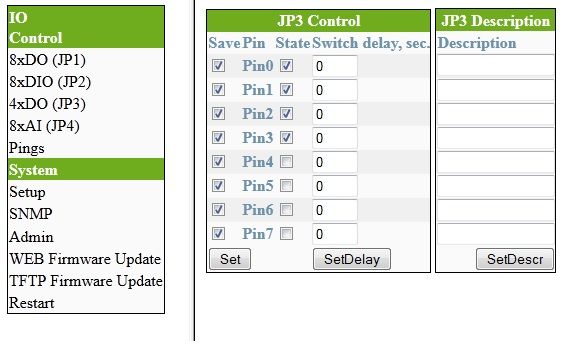
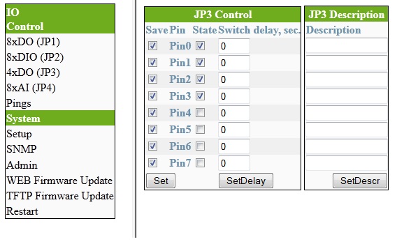
Access DAEnetIP1 via Web Browser
DAEnetIP1 has internal web server for access and configuration of almost all parameters. It can be accessed via any browser supporting javascript. It is tested with Internet Explorer, Firefox, Chrome, Safari. It is tested with the browsers of the Android and iPhone mobile devices and works well.
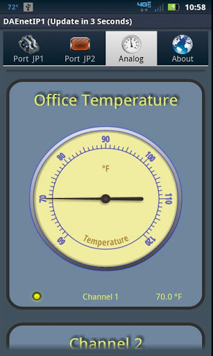
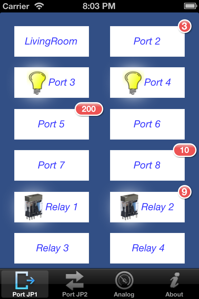
Access from Mobile Devices
The DAEnetIP1 controller and all devices based on this controller can be controlled by almost all knds of mobile devices. The applications we offer allow controlling the DAEnetIP1 digital outputs, polling the analog and digital inputs, timers for the outputs can be set as well. Please refer to the specific application description on its corresponding marketplace for more details.
DAEnetIP1 device controlled by mobile devices
| Platform | Download link | Developer | Documentation | Screenshot |
| Android |  |
 |
||
| iOS |
|
 |
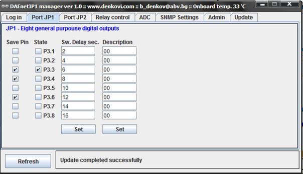
Access JP1 via DAEnetIP1 manager
DAEnetIP1 Manager is SNMP v1 configuration/control/monitor utility for DAEnetIP1. It supports many functions of the controller but not all. It works as sending/receiving snmp requests to the target DAEnetIP1 controller.
 Download the last version (install package) - DAEnetIP1Manager.exe
 Download the last version (install archive) - DAEnetIP1Manager.rar
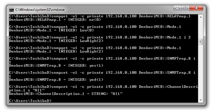
Command line (net-snmp)
Steps for Install net-snmp library in Windows. In this way you will be able to control the ethernet controller with command line (For most Linux OS, there is built in the same snmp tool in the kernel).
- Download the last version net-snmp binary for windows from http://net-snmp.sourceforge.net/download. The file must look like net-snmp-X.X.X.X-X.win32.exe
- Install the downloaded file. Leave the default options. The packet will be install in c:\usr by default.
- Download the DAEnetIP1 MIB file from here
- Copy the mib file here c:\usr\share\snmp\mibs
- Add new line in the file c:\usr\etc\snmp\snmp.conf with the "mibs all" directive.
- Now you can test different commands for OID access, supported by this module. Their names you may see in the DAEnetIP1.mib file.
- You can find example commands in the DAEnetIP1 user's manual
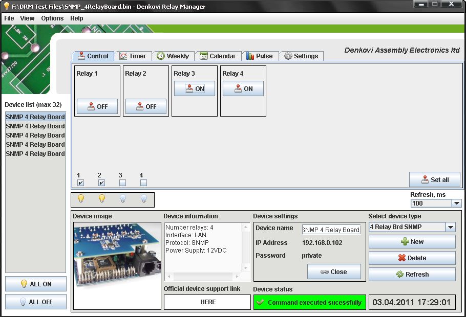
Access via DRM Software
DRM Software is Windows/Linux software for controlling all our relay boards. Supported OS:
Windows: tested on XP, Vista, 7 and 8
Linux: tested on Ubuntu and OpenSuse
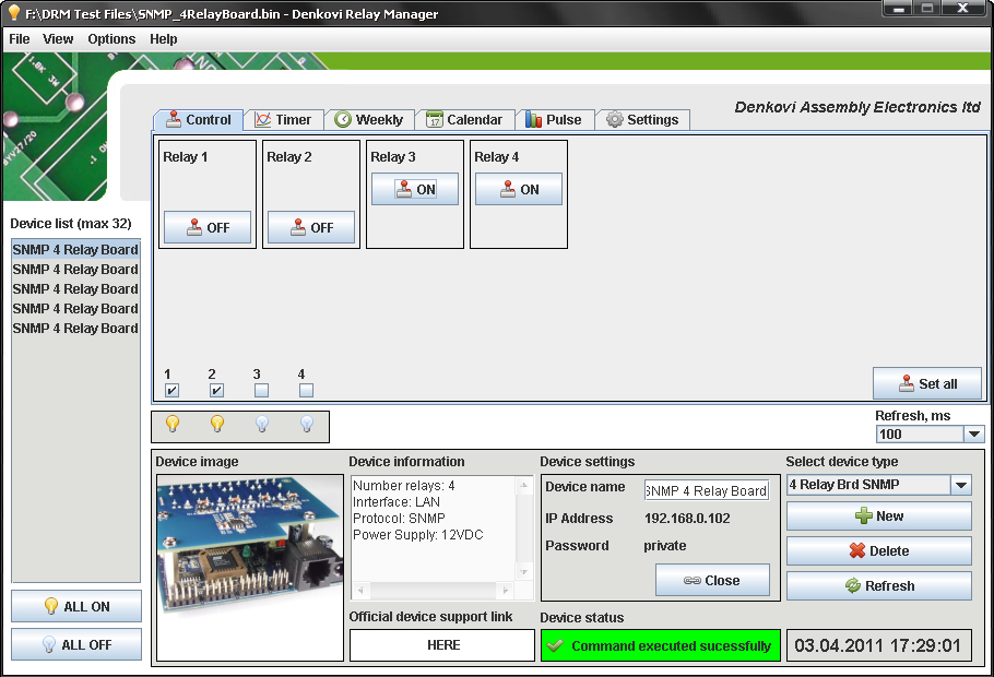
DRM Software image - control mode for Internet / Ethernet Four Channel Relay Board
![]() For more information about DRM Software, documentation and download - here
For more information about DRM Software, documentation and download - here
![]() Download the last version (install package) - DRMsetup.exe
Download the last version (install package) - DRMsetup.exe
![]() Download the last version (intstall archive) - DRMsetup.rar
Download the last version (intstall archive) - DRMsetup.rar
Demo Video
Demo video - DRM Software and Internet / Ethernet Four Channel Relay Board
Useful links
- General links
- Software by Denkovi
 DAEnetIP1 Manager support page - here
- DRM Software support page - here
- DAEnetIP Burner page (software for firmware upgrade) - here
- Software examples
- Third parity software
- Net-snmp command line tool for windows (instructions how to install - see in the manual) and C++ library - here (example commands - in the user manual).
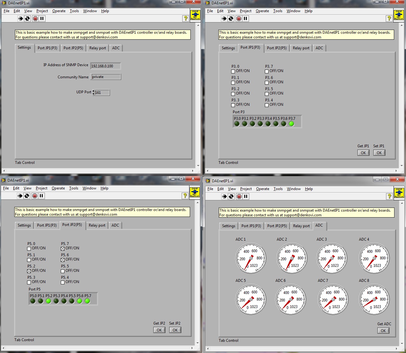
- Java (Netbeans) - Example for accessing DAEnetIP1 controller. Works in Linux / Windows / Mac
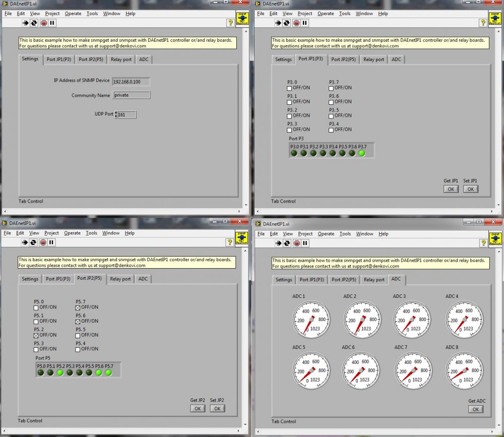
- labVIEW 2011 - basic snmp manager for DAEnetIP1 build with labVIEW. For download please contact us
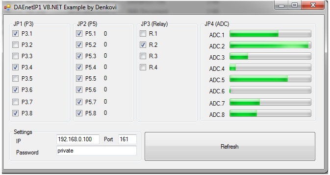
- VB .NET Express 2010 - Very simple demo. It demonstrates how to set and get DAEnetIP1 ports values. For download please contact us
-
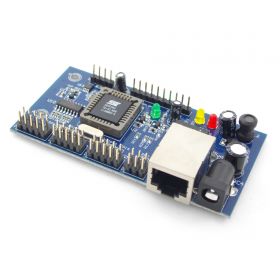
DAEnetIP1 - SNMP Ethernet controller with 28 digital/analog I/O
DAEnetIP1 is autonomic network device (IP controler), supporting 10/100 Mb/s Ethernet interface with 12 (8+4) digital outputs, 8 digital inputs/outputs and 8 analog inputs. Just connect the device into your local network and control electrical devices or monitor sensors from another computer or mobile device via Internet. We provide large number of software applications and for developers there are lot of source code examples in Java, .NET, Labview, PHP. It can be used successfully for home automation, industrials, sensor monitoring, controlling relay boards or embedding in larger systems.
Price: $58.00Out of stock -
Web SNMP controlled 8 Relay Board v1
Set of IP SNMP controller and Eight channel Relay board. The system may be controlled by WEB browser, windows application, Android software and SNMP commands.
Price: $77.30Out of stock


